
Description
Product Overview
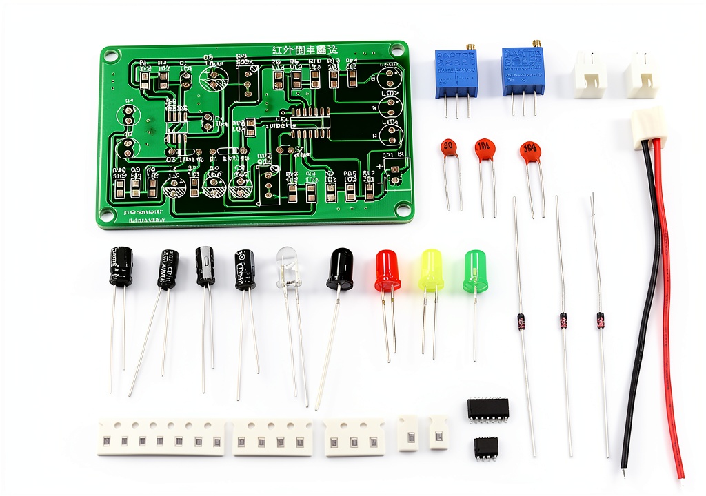
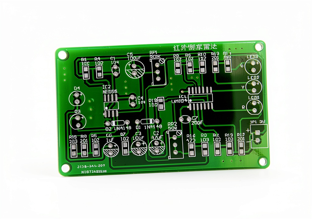
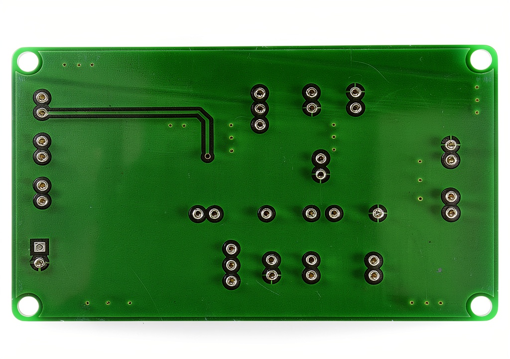
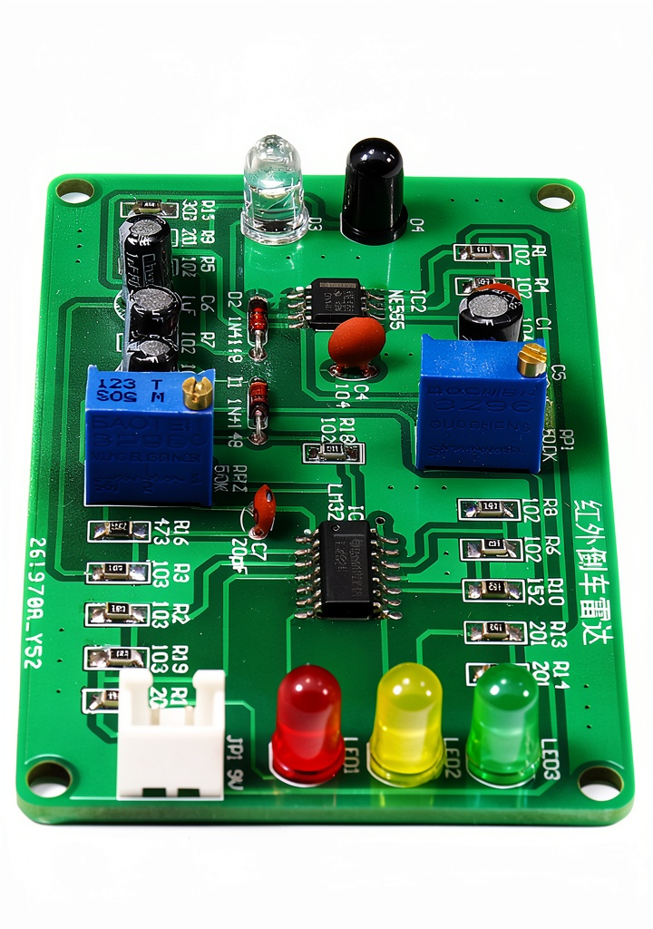
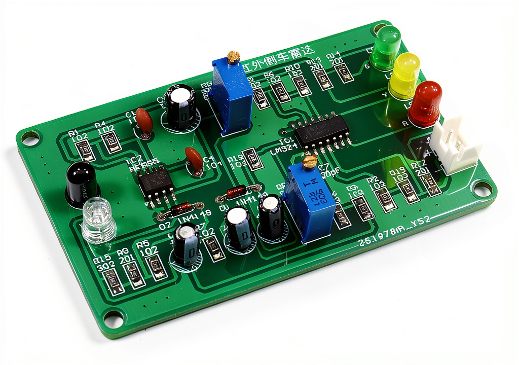
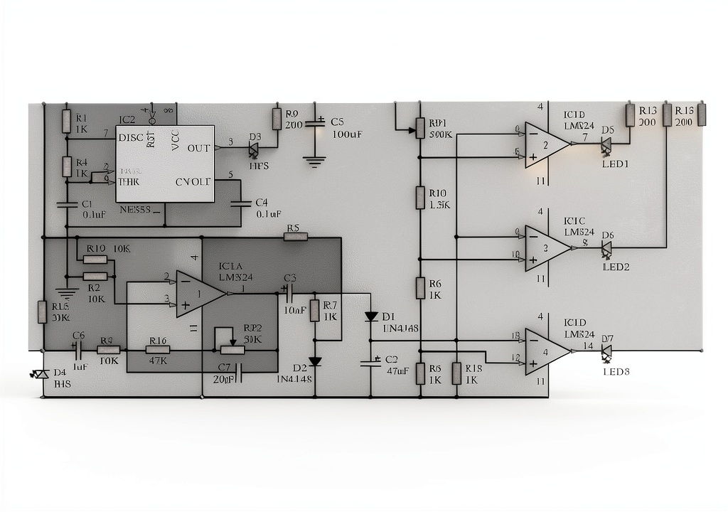
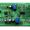
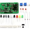
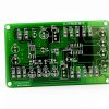
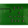
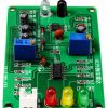
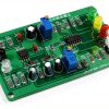
The EK1950 infrared reversing radar board combines a multi‑resonant circuit with an LED display to deliver reliable ranging functionality in a compact form factor. Constructed on a high‑quality printed circuit board, each component is clearly labeled, simplifying the soldering process for novices and experienced makers alike. Key specifications include a weight of 0.634 oz, dimensions of 3.5 × 2.8 × 0.2 in, and an internal USB port for power and data connectivity. Designed for educational environments, the board supports a variety of infrared signal transmission and reception experiments, making it a versatile tool for learning about signal processing and distance measurement.
Usage
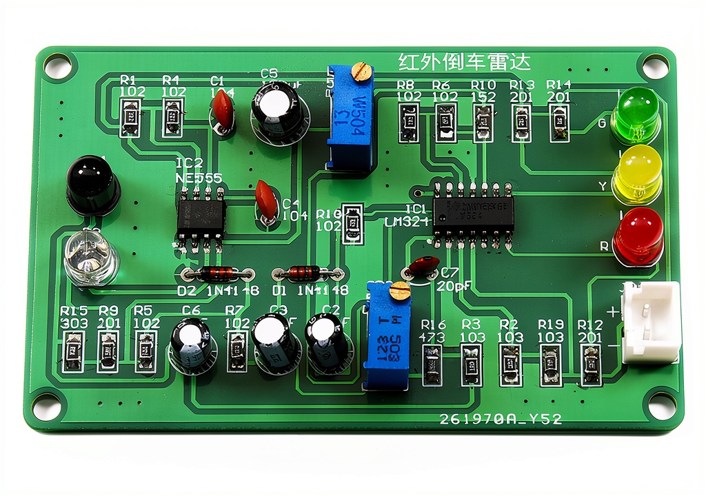
This board is ideal for electronics classrooms, maker spaces, and hobbyist workshops where hands‑on learning is emphasized. Students can integrate the radar into robotics projects, obstacle‑avoidance systems, or simple distance‑measurement demonstrations. The LED display provides immediate visual feedback, allowing users to observe signal strength and range in real time. Its simple circuit design ensures stable operation across a range of experimental setups, from basic lab exercises to more advanced prototype development.
Why Choose Us
Our radar board stands out due to its robust PCB construction, clear component markings, and comprehensive support resources. Each unit includes an online PDF guide that walks users through assembly, testing, and troubleshooting, and our technical team is ready to assist with any questions. The board’s multi‑resonant circuit delivers consistent performance, while the LED interface enhances usability for learners. By focusing on durability and educational value, we provide a reliable platform that grows with the user’s skill level.
Key Features
- Multi‑resonant infrared circuit for accurate ranging
- Clear LED display for instant visual feedback
- High‑quality PCB with labeled components for easy soldering
- Compact size and lightweight design for portable projects
- Comprehensive PDF guide and responsive technical support
FAQ
What is the recommended soldering technique?
Use a fine‑tip soldering iron with lead‑free solder, following the step‑by‑step instructions in the PDF guide to ensure clean joints on the labeled pads.
Can the board be powered via USB?
Yes, the internal USB port supplies 5 V power and allows data communication for debugging and firmware updates.
Is the board suitable for advanced robotics projects?
Absolutely. Its stable infrared ranging and LED feedback make it a solid foundation for obstacle‑avoidance and distance‑sensing modules in robotics.
What support is available if I encounter assembly issues?
We provide an online PDF manual and a responsive support team that can help troubleshoot soldering or circuit problems via email or chat.
Does the board work with other microcontrollers?
The board’s interface is compatible with common microcontrollers such as Arduino, Raspberry Pi, and ESP32, allowing easy integration into diverse projects.



Reviews
There are no reviews yet.